Metals
Aluminium (6061, 7075, 7050, 5052, 5083, 6082), stainless and alloy steels (304, 316, 17-4PH, 4140, 42CrMo), titanium Ti-6Al-4V, brass and copper.
Materials guide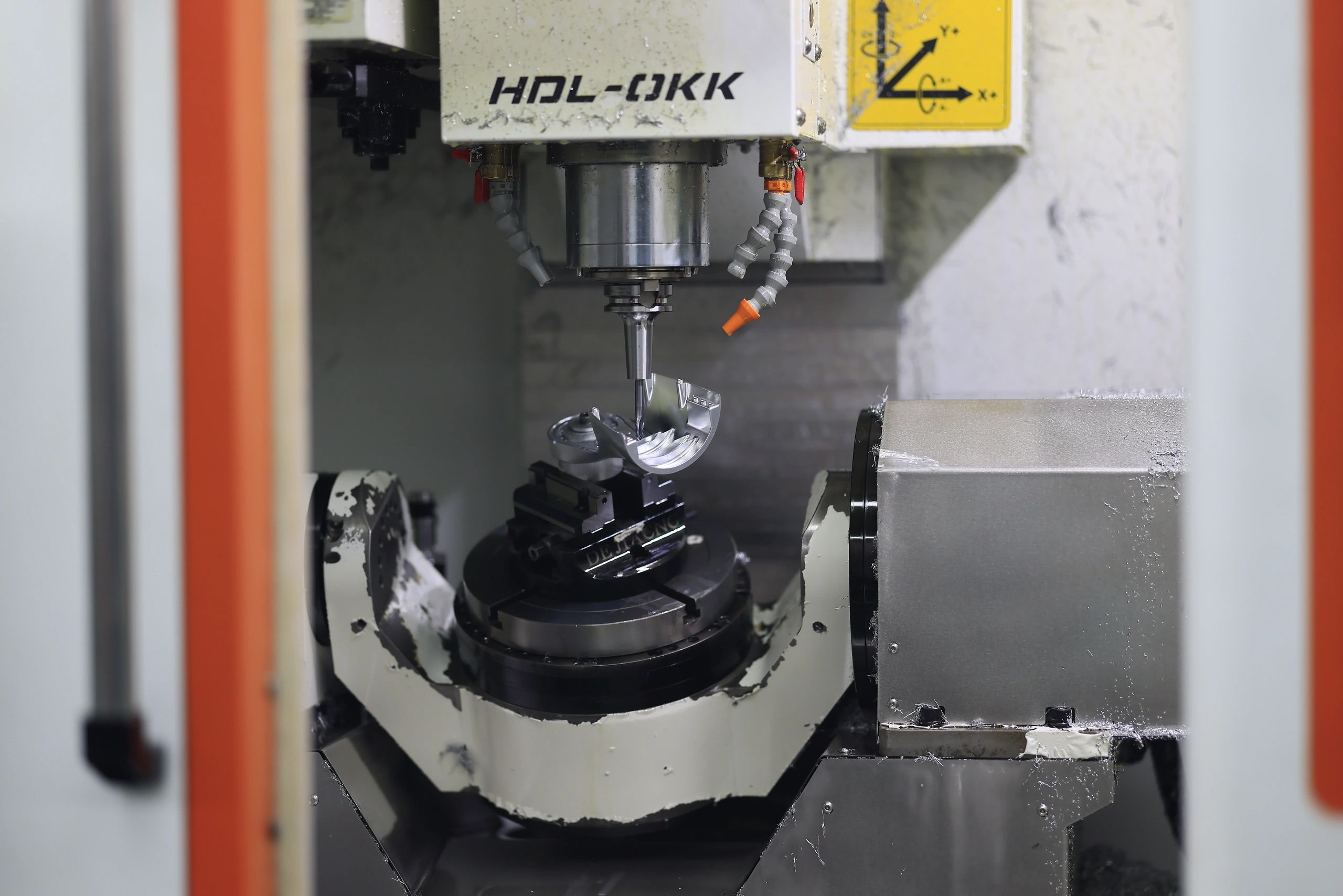
CNC Milling
3-, 4-, 5-axis and 3+2 CNC milling for complex, tight-tolerance parts in metals and engineering plastics.
The basics
CNC milling is a subtractive process: computer-controlled rotary cutting tools remove material from a solid block to produce a finished part. It suits complex geometries, tight tolerances and a wide range of metals and engineering plastics, from one-off prototypes to repeatable production runs.
An axis is a direction in which the machine can move the tool or the part. A 3-axis machine moves in X, Y and Z. 4- and 5-axis machines add rotation, letting the tool reach more faces of a part in a single setup, which improves accuracy and lowers cost on complex geometry by reducing re-fixturing.
Machine envelope
Across our 5-, 4-, 3+2 and 3-axis machines. Achievable results depend on geometry and material, confirmed at DFM review.
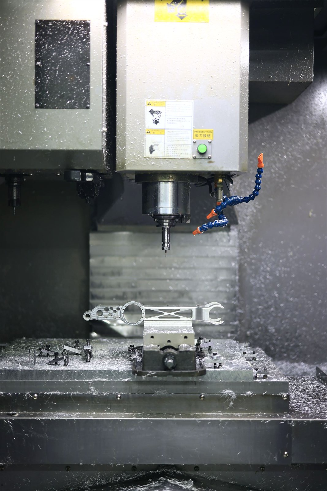
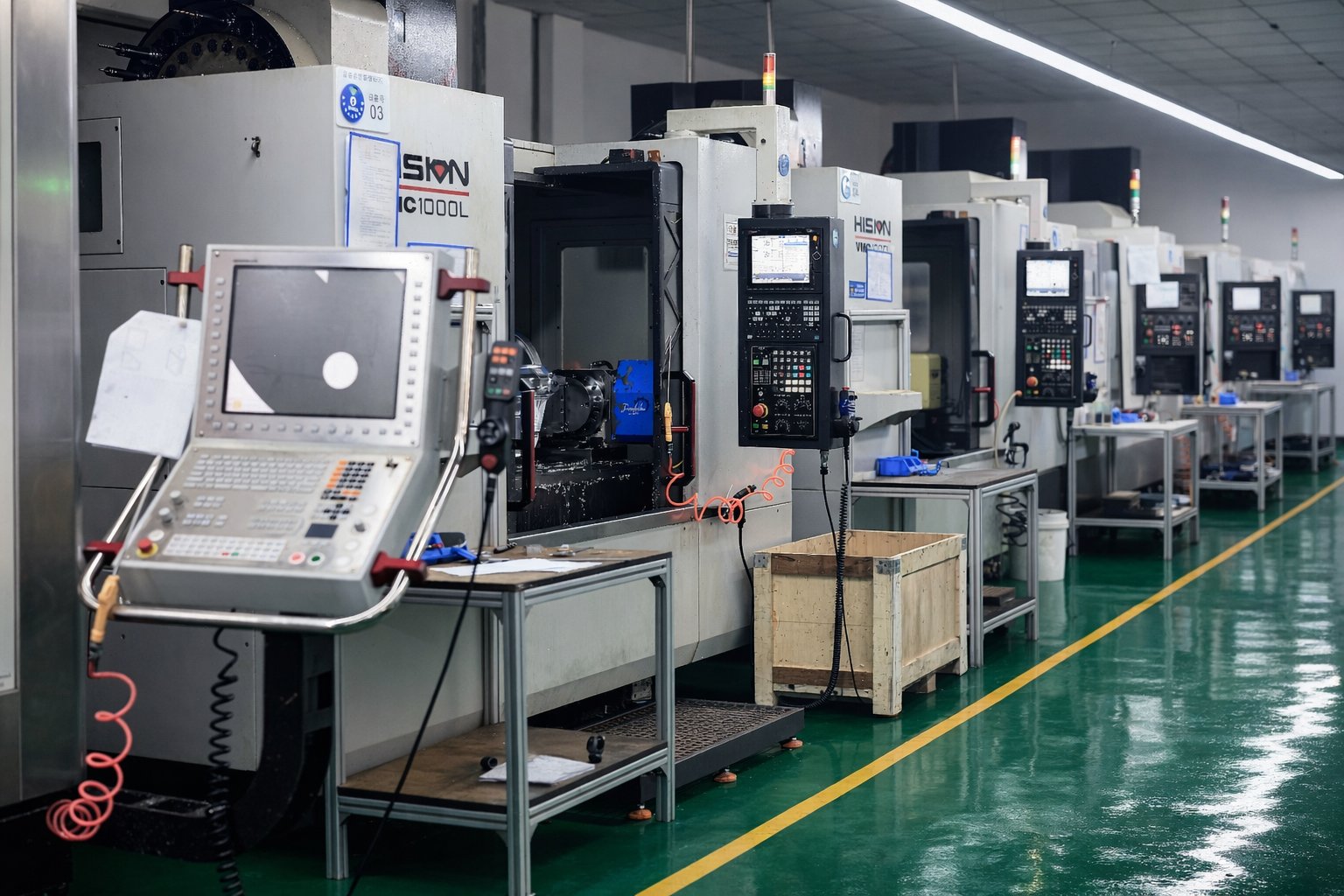
Precision milling of an aluminium contoured part on a 3-axis machining centre, the everyday work behind the envelope figures below.
| Configuration | Max part envelope | Min feature | Default roughness |
|---|---|---|---|
| 5-axis | 2000 × 1200 × 800 mm | Ø0.50 mm | Ra 3.2 µm |
| 4-axis | 1000 × 500 × 370 mm | Ø0.50 mm | Ra 1.6 µm |
| 3+2 indexed | 700 × 400 × 350 mm | Ø0.50 mm | Ra 3.2 µm |
| 3-axis | 2500 × 1200 × 800 mm | Ø0.50 mm | Ra 1.6 µm |
If you need a finer surface roughness than the default, mark it on your drawing.
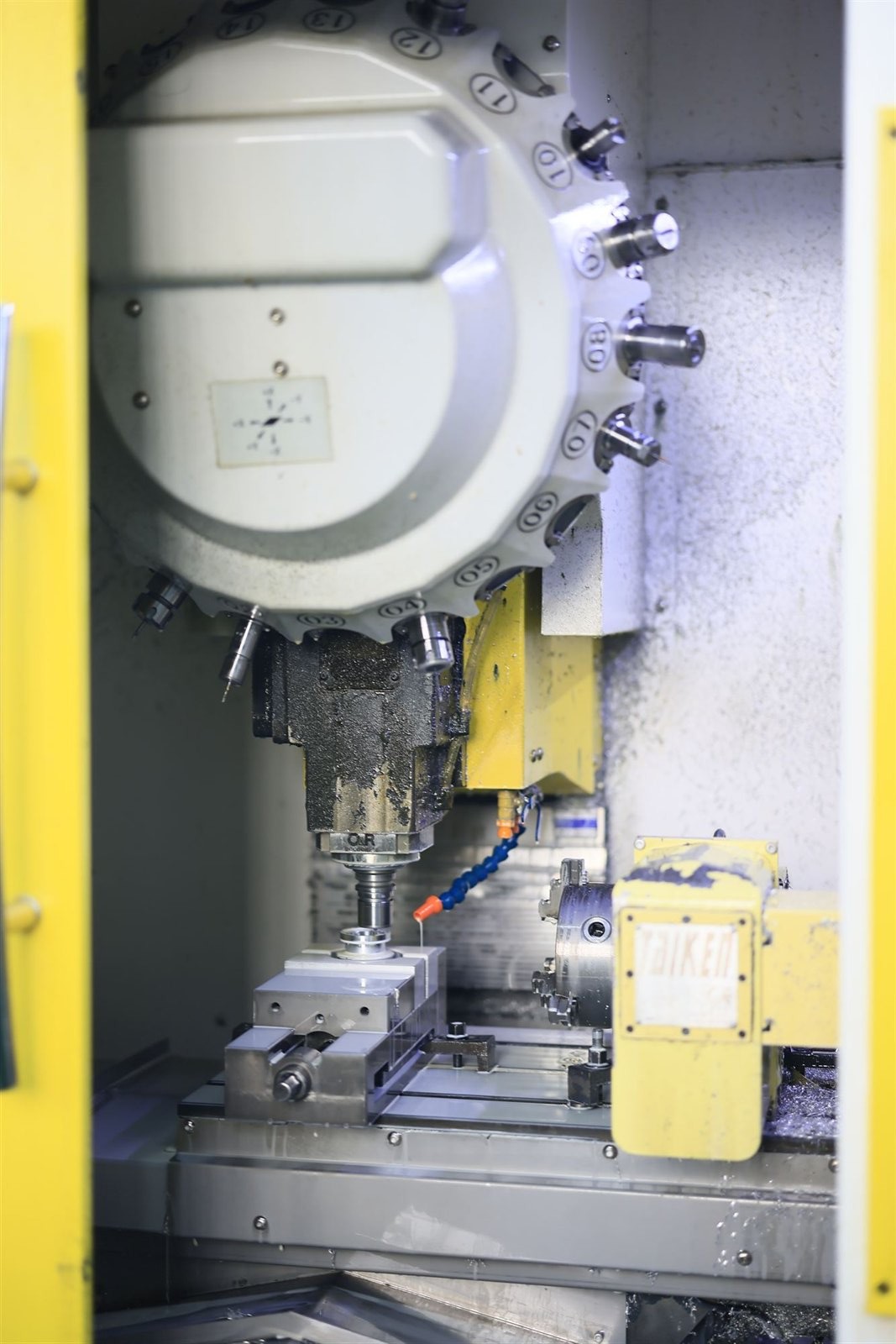
An automatic tool changer feeds the spindle inside each machining centre, so multi-tool programs run unattended while holding the same setup and datum.
Materials
Common grades are stocked; others are sourced with certification and full traceability.
Aluminium (6061, 7075, 7050, 5052, 5083, 6082), stainless and alloy steels (304, 316, 17-4PH, 4140, 42CrMo), titanium Ti-6Al-4V, brass and copper.
Materials guidePEEK, PA6 (nylon), POM (acetal) and PTFE, for lightweight, wear-resistant and chemically resistant parts.
Materials guideSurface finishes
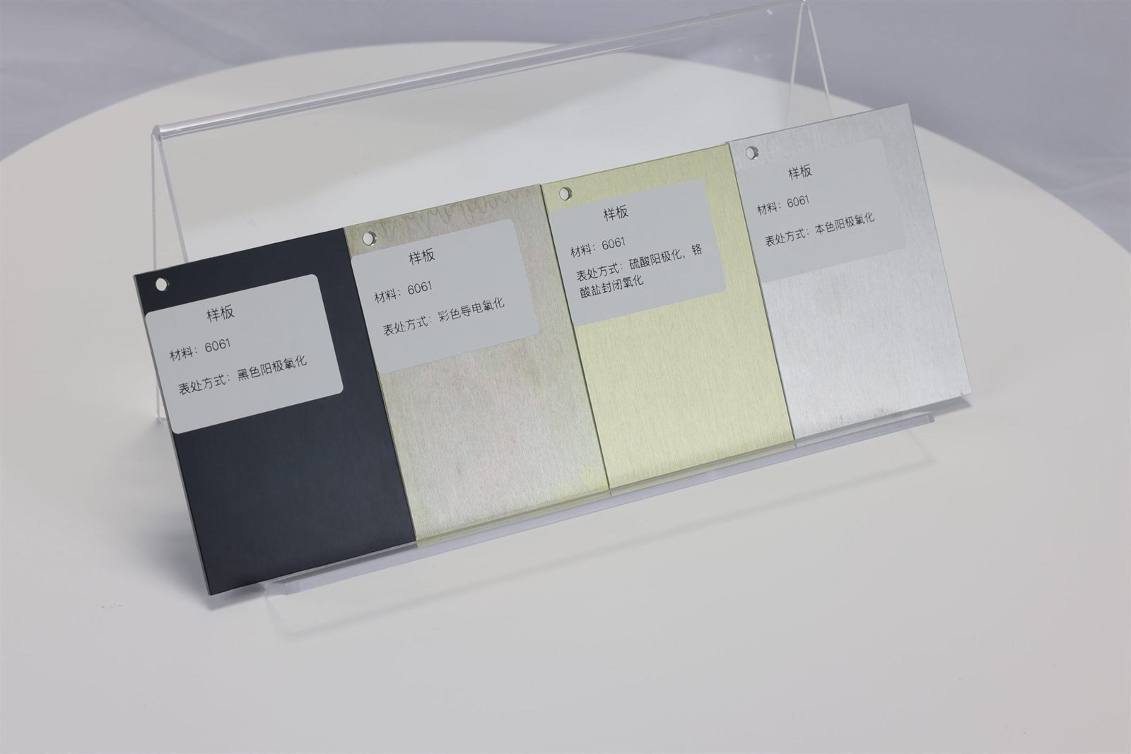
As-machined, bead-blast, brushed, anodizing (clear, colour, Type II / III), plating, passivation and powder coat, matched to the function and look your part needs.
Finishing optionsTolerances
We work to ISO 2768-m (medium) as standard. Tolerances down to ±0.005 mm are available on request, ±0.005 mm is not the default. Mark any tighter tolerances directly on your drawing and our engineers confirm feasibility at DFM review.
Tolerance standard
Mark critical tolerances on your drawing, we confirm feasibility at DFM.
Quality
All inspection is in-house — first-article (FAI), in-process and a final sampling check (typically ~5%, more on small runs) before it ships; full 100% inspection on request.
Dimensional and CMM inspection reports are issued with your parts on request.
Quality management certified to ISO 9001, IATF 16949 and AS9100D.
IP protection
Drawings, models and part data are kept confidential and not shared with third parties. An NDA is available on request, and we are happy to sign first.
How we work together
Eight clear steps, with typical lead times so you can plan.
Send your drawings (STEP, IGES, X_T or PDF) with quantity, material and finish. NDA on request.
A detailed, line-item quote with lead time, typically within 48 hours.
DFM feedback on tolerances, features and material to cut cost and risk before machining begins.
Order confirmation, certified material procurement, fixturing and CAM programming.
Machining with first-article and in-process checks against your drawing.
Final in-house inspection — a sampling check (typically ~5%, more on small runs); full 100% inspection on request. CMM and dimensional reports available.
Protective packaging, full traceability and worldwide shipment.
Ongoing engineering support and repeat-order planning as you scale.
Get started
Send your drawings and our engineering team reviews your design and quotes within 48 hours, no minimum order.
Your drawings stay confidential.