A planetary reducer achieves its torque density by dividing load across several planets instead of one gear pair. Accurate pin location in the carrier helps the planets share that load as intended; position errors can cause one planet to engage more heavily than the others, reducing fatigue life.
Real load sharing also depends on gear errors, carrier deflection, pin flexibility, bearing stiffness and any floating members in the design. The carrier is one of the larger contributors a machine shop controls directly.
What the carrier actually controls
The carrier is a structural part with a metrology job. It holds each planet pin at a fixed radius and a fixed angular spacing, keeps the two flanges square to the output axis, and transmits the resulting torque to the output shaft. Every one of those functions is a machining feature:
- Pin-bore position — radius and angular spacing, which influence which planet begins carrying load first and how the load divides.
- Bore-to-bore consistency — the bores must match each other, not just their nominal size.
- Alignment of corresponding pin bores in the two flanges — misalignment tilts the planet pin relative to the gearbox axis.
- Perpendicularity of the flange faces to the gearbox datum axis, and parallelism between opposing flange faces where the assembly requires it.
- The output interface — spline or bolted flange, located relative to the same functional datum system.
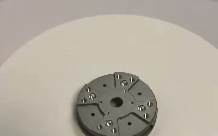
A carrier plate with its pin pattern. Gearset alignment and load distribution depend in part on where those holes end up relative to each other and to the output axis.
How pin-bore position affects load sharing
If every planet pin were positioned exactly as designed, the planets would share the load more evenly. In practice there is always some residual position error, and a pin-position error can cause one planet to enter load earlier than the others and carry a disproportionate share of the load.
Gear-design literature often analyses pin-spacing errors in the tens-of-micrometres range in published examples, with planet bores matched to each other within single-digit micrometres in some published load-sharing studies, and examines pin-position standard deviations of a few micrometres.
These are illustrative figures from published analysis and should not be used as general drawing tolerances. The required tolerance for a given design depends on gear geometry, architecture, stiffness and the target load-sharing factor. What does generalise is the direction: for load sharing, consistency in pin-axis position is often as important as the individual bore-diameter tolerance.
Why the two flanges are bored together
Most carriers are a two-plate structure — a flanged body and a cover, or two flanges joined by webs — and each planet pin spans both. If the two halves are bored in separate operations, the pin's parallelism to the output axis depends on the agreement between two setups. Inspection can identify the resulting error, but it cannot eliminate the setup-to-setup tolerance stack.
A common approach is to clamp the flanges together in their assembled relationship and bore the pin holes through both at once, so their alignment is established in the same machining setup rather than through two independent setups. It costs a fixture and a dedicated operation, and it reduces one of the major process-related sources of pin-axis misalignment. For designs where pin alignment is critical to load sharing, machining the corresponding bores in one setup is generally the preferred process.
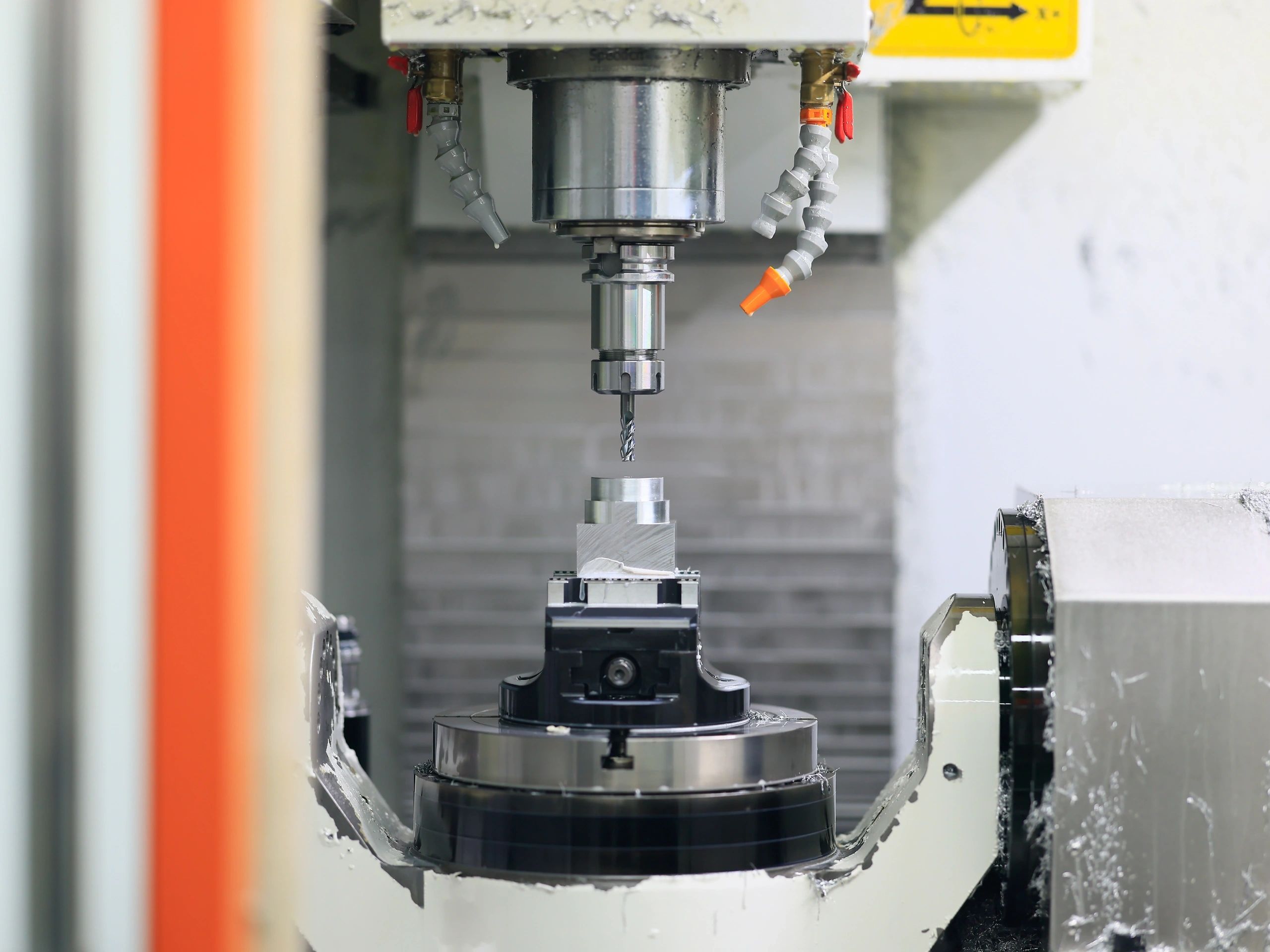
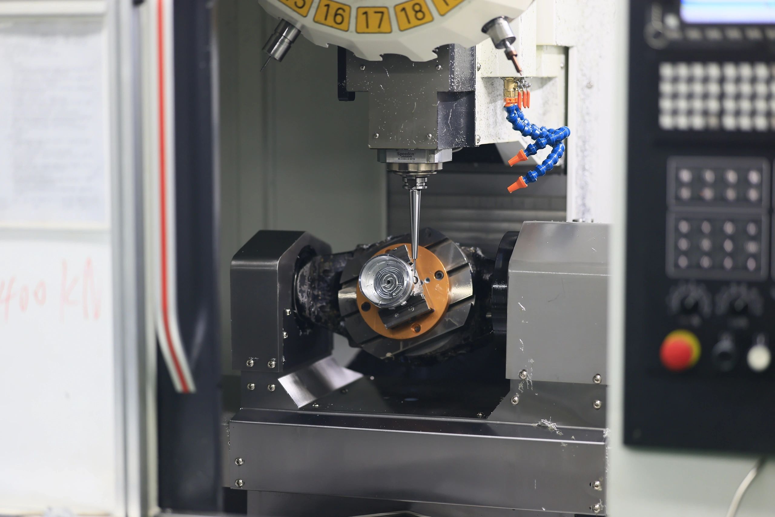
We do the same thing in a different way for one-piece carriers: bore the pin holes, the output interface and the bearing seats in a single simultaneous 5-axis setup, so their relationship is controlled within one coordinate system, reducing error introduced by repeated re-fixturing.
Parallelism, perpendicularity and the face relationship
A carrier can meet individual size tolerances and still fail functionally if the geometric relationships are out of tolerance. The flange faces have to be perpendicular to the datum axis, parallel to each other where the assembly requires it, and flat enough that bolting the assembly together does not pull the pins out of line.
Bolt-up distortion is a real failure mode: a carrier that measures within tolerance in the unassembled condition can move out of tolerance after the assembly is bolted and torqued.
This is why carrier drawings usually include more geometric callouts than size callouts, and why the inspection report should verify the relevant geometric relationships, not only individual dimensions. Where a feature is functional, it is worth tolerancing it geometrically and stating the datum it references.
Material, and what it means for the finish
| Material | Chosen when | Machining / finish note |
|---|---|---|
| 6061-T6 aluminium | Applications sensitive to weight and rotating inertia; moderate torque. | Good machinability for tight-tolerance bores. If anodized, the film closes the bores — see below. |
| 7075-T6 aluminium | Higher strength at the same weight. | Stronger but less corrosion-tolerant; anodize behaviour differs from 6061. |
| Structural steel (e.g. S235JR / 1.0038) | Higher-load, cost-sensitive applications where mass is less critical. | Bare carbon steel can develop surface rust during storage or transport, particularly in humid conditions — specify an appropriate coating, protective oil or other corrosion-protection method; if none is specified, we can confirm the requirement before production. |
| Case-hardening steel | Where pin bores see high contact stress. | Heat treatment can introduce distortion; critical bores are finish-ground or hard-turned afterwards. |
A carrier drawing with no surface-treatment callout is a question rather than a default, so we ask rather than assume. This matters most on steel components, where an omitted surface-treatment note can result in corrosion during storage or transport.
If the carrier is aluminium and anodized
Part of the anodic coating builds up outward from the bore surface, so the bore closes. The nominal build-up differs by process — roughly a third of the coating thickness for Type II, about half for Type III — so a 3–5 µm Type II coating typically closes a bore by only a few micrometres, while an 8–25 µm hardcoat can take up much of an H7 band before any machining variation is counted.
Where that matters, the bores are normally masked, machined oversize by a calculated allowance, or finish-machined after coating.
Carriers frequently also need bare-metal areas for a ground path or a sensor reference. The full treatment of that is in bare-metal contacts on anodized parts.
Where backlash actually comes from
Backlash is a system-level characteristic influenced by gear accuracy, bearing arrangement, preload, fits, carrier geometry and assembly. The carrier is one contributor rather than the sole determining component.
In practice, carrier accuracy cannot compensate for errors in the other gear components, but carrier error can compromise the performance of an otherwise accurate gearset.
How we machine and verify them
Where geometry allows, carriers are machined in a 5-axis setup so the pin pattern, output interface and bearing seats can be established within the same coordinate system. Our 5-axis machining envelope is 2000 × 1200 × 800 mm and our 3-axis envelope is 2500 × 1200 × 800 mm, with turning to Ø500 × 580 mm for associated shafts and flange components for reducer assemblies.
Verification is on a temperature-controlled CMM — SEREIN CROMA-776, 700 × 700 × 600 mm measuring volume, Renishaw PH10T motorised probe head — reporting pin-bore position, parallelism, perpendicularity and the flange relationships as a set rather than as isolated dimensions. Certification is ISO 9001:2015, IATF 16949:2016 and AS9100D / EN 9100:2018, with material traceable by batch.
Related reading: robot actuator housing machining, tolerances and ISO 2768, and the industry page for robotics CNC machining.
Common questions
Why does carrier accuracy matter so much?
A planetary set earns its torque density by dividing load across several planets, and the carrier establishes the location of each planet pin. A severely mispositioned pin can cause its planet to enter load earlier and carry a disproportionate share, and can become one factor limiting fatigue life or load capacity.
What pin-bore tolerance does a carrier need?
It depends on ratio, module and duty. Gear literature commonly cites pin spacing in the region of a few hundredths of a millimetre with the bores matched to each other within single-digit micrometres where load sharing is critical. The right number for your gearbox comes from your own load-sharing analysis; we machine and verify to the print.
Why bore both flanges in one setup?
Every re-fixturing makes the relationship between the flanges depend on how well two setups agreed rather than on the machine's positioning. Machining the corresponding bores in one setup establishes their relationship within the same coordinate system and reduces cumulative error from separate setups.
Do you machine steel carriers as well as aluminium?
Yes. Aluminium where inertia and weight dominate, structural or case-hardening steels where pin seating and torque capacity dominate. Note that bare carbon steel can develop surface rust during storage or transport unless a coating or protective oil is specified.
Does anodizing affect the pin bores?
Yes, on aluminium carriers with toleranced bores. Part of the coating builds up outward from the bore surface — nominally about a third of its thickness for Type II, about half for Type III — so the bore closes. On hardcoat that can take up much of an H7 band, so the bores are normally masked, machined oversize, or finish-machined after coating.