In a robot joint, the bearing seat is where a tolerance class on the drawing becomes a physical fit. When it is right, the bearing presses home, runs true and stays put. When it is a few microns wrong, the bearing either will not seat or starts to creep in its bore once the joint warms up.
This guide covers the ISO 286 classes most often specified on robot bearing seats, what they mean in microns at common robot bore sizes, and three things that change the result between the drawing and the assembled joint: an aluminium housing around a steel bearing, the geometry between paired bores, and anodize. Thin walls, flange flatness and bare bonding zones are covered separately in our guide to robot actuator housing machining.
The fits that appear on robot bearing seats
Across the joint, gearbox and motor housings we machine for robot actuators, mostly in 6061-T6, the outer-ring seats use a fairly small set of classes. H7 is the most common. J7, M7 and N7 appear where the outer ring must not move, P6 on small pressed bores, and U6 where a ring or sleeve is pressed in permanently. On the mating shafts, often 4140 quenched and tempered steel, the inner-ring seats are usually k5, k6 or p6.
The letter positions the band relative to the nominal size; the number sets its width. H7 starts at nominal and only goes up. N7 sits entirely below nominal. The band also widens with size, so the same class means different microns on different bores:
| Class | Ø30 | Ø47 | Ø52 / Ø57 |
|---|---|---|---|
| H7 | +21 / 0 | +25 / 0 | +30 / 0 |
| J7 | +12 / −9 | +14 / −11 | +18 / −12 |
| M7 | 0 / −21 | 0 / −25 | 0 / −30 |
| N7 | −7 / −28 | −8 / −33 | −9 / −39 |
| P6 | −18 / −31 | −21 / −37 | −26 / −45 |
For shaft seats the bands sit above nominal: at Ø20 (over 18 up to 30 mm), k5 is +11 / +2 µm, k6 is +15 / +2 µm and p6 is +35 / +22 µm; at Ø40 (over 30 up to 50 mm), k5 is +13 / +2, k6 is +18 / +2 and p6 is +42 / +26 µm.
What the class means once the bearing is in it
The bearing has a tolerance of its own. For a normal-tolerance-class radial bearing, the mean outside diameter is 0 / −11 µm over Ø30–50 mm and 0 / −13 µm over Ø50–80 mm. Putting the two together gives the fit the assembler actually sees:
| Housing class | Ø47 seat | Ø52 seat |
|---|---|---|
| H7 | 0 to 36 clearance | 0 to 43 clearance |
| J7 | 11 interference to 25 clearance | 12 interference to 31 clearance |
| M7 | 25 interference to 11 clearance | 30 interference to 13 clearance |
| N7 | 33 interference to 3 clearance | 39 interference to 4 clearance |
H7 is a clearance fit: the ring slides in and can be removed, which suits a floating bearing or an outer ring that is stationary relative to the load. N7 is almost entirely interference: the ring is pressed and will not creep, but the press fit also reduces the bearing's internal clearance, which the bearing selection has to allow for. J7 and M7 sit in between. Bearing makers build their fit tables around one question, whether the load rotates relative to the ring: a rotating load calls for an interference fit, a stationary load for a transition or loose fit. That choice belongs to the designer; our job is to hold whichever class is on the drawing.
Aluminium housing, steel bearing
Robot housings are usually aluminium and bearings are steel, and the two do not expand together. 6061-T6 expands about 23.6 µm per metre per kelvin (20–100 °C); 52100 bearing steel about 11.9 µm/m·K. The difference is roughly 11.7 µm/m·K.
On a Ø47 seat, a uniform rise of 40 °C above assembly temperature opens the bore by about 22 µm relative to the ring, close to the full width of the H7 band at that size. A fit that is a light transition fit on the bench can become a clearance fit in a warm joint, and an outer ring with clearance under a rotating load can creep. This is why bearing makers recommend tighter fits in light-alloy housings than their tables give for steel or cast iron. The opposite applies in the cold: an interference that is comfortable at room temperature tightens further. A seat fit is worth checking at both ends of the joint's operating range, not only at 20 °C.
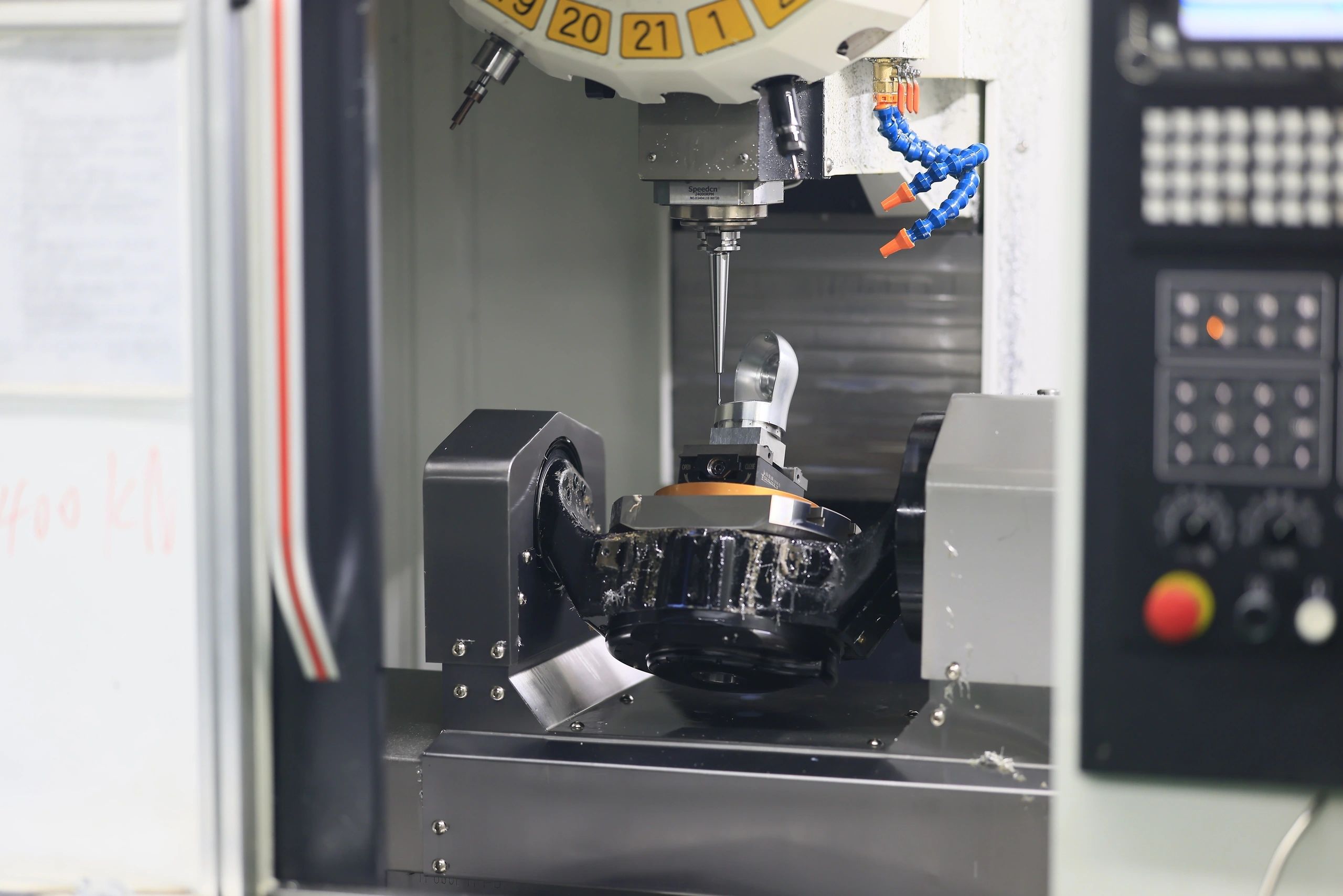
A robot joint part on a 5-axis trunnion. Features that must share an axis are best cut without re-clamping between them.
Two bores, one axis
Each seat can be in size and the pair can still fail. If the two bearing seats in a housing are not on a common axis, the shaft forces the bearings out of line as soon as it is assembled, and no single-bore measurement will show it. On the actuator housings and shafts we machine, drawings commonly carry coaxiality of 0.01–0.02 mm between paired seats, cylindricity of 0.0055–0.015 mm on the bearing bores themselves, and positional tolerances of 0.013–0.05 mm to the datums. Drawings for the 4140 shafts that run in these housings have called for total runout as tight as 0.004 mm across the bearing seats.
Cylindricity matters because a bore can measure in size at the entry and still taper, barrel or lobe along its length. A bearing ring is stiff; it meets the narrowest section of the bore first. Size, form and axis are three separate requirements, and a bearing seat needs all three on the drawing. For how general and functional tolerances work together, see our guide to CNC tolerances and ISO 2768.
How the bores are measured
- Two-point bore gauges give a fast local diameter at the machine and are useful for in-process size checks. On their own they do not report cylindricity or where the bore axis sits.
- CMM measurement establishes the axis of each bore, so size, cylindricity, coaxiality and position can be reported against the drawing datums. This is where paired-bore requirements are confirmed.
- Temperature. Aluminium moves quickly: a Ø47 bore in 6061 changes by about 1.1 µm for each degree Celsius. Dimensions are referred to the standard reference temperature of 20 °C (ISO 1), which is why we measure in a temperature-controlled lab.
Every order receives first-article, in-process and final inspection on CMM and 2.5D optical VMM, with dimensional, CMM and FAI reports available on request.
Anodize and the bore
Anodizing converts the surface into oxide: part of the film penetrates the metal and part builds up above the original surface. The Aluminum Anodizers Council gives the split for Type III hardcoat as about 50% penetration and 50% build-up per surface. For conventional Type II, the outward share is usually quoted lower, closer to a third, and it varies with alloy and process. Because a bore builds up on both sides, its diameter closes by about twice the per-surface build-up.
With our usual thicknesses, a 3–5 µm Type II film closes a bore by roughly 2–3.5 µm. An 8–25 µm Type III hardcoat closes it by roughly 8–25 µm, which on a Ø47 H7 seat (a 25 µm band) can consume the whole tolerance. Note also that MIL-A-8625 allows Type II coatings from about 1.8 to 25 µm, so "Type II" alone does not tell the machinist how much a bore will close; the thickness, or masking, should be stated.
On the robot housings we make, bearing bores are typically masked through black anodize, and features that must be bare and exact are finish-machined after anodizing. The drawing should say whether bore dimensions apply before or after coating and which bores are masked. The coating options themselves are compared in anodizing Type II vs Type III.
How we work on robot housings
We machine robot joint, gearbox and motor housings and their shafts from prototype sets of 1 to 15 through production batches of 100 or more, on the same floor. Milling features can be held to ±0.005 mm where the function requires it, and turning to ±0.01 mm. Certification is ISO 9001:2015, IATF 16949:2016 and AS9100D / EN 9100:2018, with material traceability. Quotes in 48 hours, no minimum order, and an NDA is available on request.
Related reading: robot actuator housing machining, anodizing Type II vs Type III, and the industry page for robotics CNC machining.
Common questions
What tolerance should a bearing bore in an aluminium robot housing have?
H7 is the most common class on outer-ring seats, with J7, M7 or N7 where the outer ring must not move under load. The right class depends on whether the load rotates relative to the outer ring and on the operating temperature: an aluminium housing expands about twice as much as a steel bearing, so bearing makers advise tighter fits in light-alloy housings than tables written for steel or cast iron. The class is the designer's decision; we machine to the class on the drawing.
Why would a bearing not seat in a housing whose bore measures in size?
Diameter alone does not describe a seat. A bore can be in size at the mouth and still taper, barrel or lobe along its length, two paired seats can sit off a common axis, coating can build up in a bore that should have been masked, and a raised edge at the bore entry can stop the ring. That is why bearing seats need form and coaxiality callouts, not only a size tolerance.
Should bearing bores be masked during anodizing?
Usually, yes, or finish-machined after coating. Part of an anodic film builds up outward, so a bore closes by roughly twice the per-surface build-up. A thin Type II coating may close a bore by only a few microns, but a Type III hardcoat can take up most or all of an H7 band. State on the drawing whether bore dimensions apply before or after coating, and mark the bores to be masked.
How are bearing bores measured?
A two-point bore gauge gives a fast local diameter at the machine, but on its own it does not report cylindricity or where the bore axis sits. A CMM establishes each bore's axis, so size, cylindricity, coaxiality and position can be reported against the datums. Because aluminium expands quickly with temperature, measurement is done in a temperature-controlled lab and referred to the standard reference temperature of 20 °C.