Most aluminium robot structure — joint housings, hip and torso shells, joint frames, caps and arm links — ships bead-blasted and anodized. The finish is chosen for appearance, but it is applied to a part full of bearing fits, threads and grounding faces, and those have to survive it.
This guide covers how the finish is specified on robot parts: what blasting does to the look, when to use Type II colour and when Type III hard anodize, what to expect from colour consistency, how much the film grows, and which features to keep it off.
Why robot structure is blasted, then anodized
The two steps do different jobs. Bead blasting gives the bare aluminium an even matte or satin texture and evens out light machining marks, so a set of parts cut with different tools and toolpaths reads as one family. Anodizing then converts the surface into a hard aluminium-oxide layer that resists wear and corrosion and, when dyed, carries the colour. Because the anodic film follows the surface beneath it, the blasted texture shows through the finished coat.
Blast media changes the result. Fine glass bead produces a consistent, satin-like finish; aluminium-oxide grit is used before anodizing to produce uniformly matte anodized parts; and in general, the coarser the grit, the rougher the finish. Drawings in this sector often describe the target simply as "black bead-blast anodize, semi-matte". If the look matters, the most reliable specification is an approved sample, not a description.

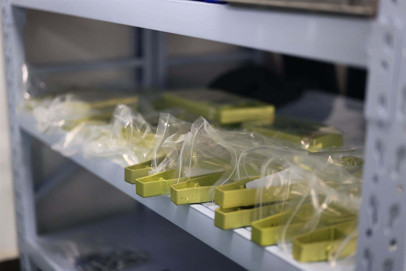
Bead-blasted aluminium before anodizing. The anodic film follows this texture, so the blast sets the final sheen.
Type II colour or Type III hard anodize
MIL-PRF-8625 (formerly MIL-A-8625) separates sulfuric-acid anodizing (Type II) from hard anodizing (Type III), with Class 1 undyed and Class 2 dyed. On robot parts the split usually follows function:
- Type II, dyed or clear for covers, shells, frames and housings where the finish is mainly cosmetic and protective. Black is the most common choice; clear (natural) and grey are also common, and other dyed colours are possible. Our usual Type II film is about 3–5 µm.
- Type III hard anodize for surfaces that see wear or sliding contact — joint motor housings, output shafts, caps that are handled or rub. Our usual hard coat is about 8–25 µm. Hard anodize is not a free colour choice: its natural tone ranges from light tan to black depending on alloy and thickness, which is why hard-anodized joint parts usually end up dark grey or black.
One specification point is worth checking: MIL-PRF-8625 expects the coating thickness to be stated on the drawing or purchase order, and if a Type III callout gives no thickness the specification assumes 0.002 in (about 50 µm) — far thicker than most robot parts need. State the thickness. The wider comparison is in anodizing Type II vs Type III.
Colour consistency: matched to a sample, not guaranteed identical
Robot programmes often want the black on this year's batch to look like last year's. Dyed anodize can get close, but it is not a paint system, and it is not reasonable to promise an exact match. The shade depends on the alloy, the film thickness, the blast and the dye lot. Alloy is the largest single factor: 7075 tends to show a yellow tint under clear anodize and does not take black as deeply as 6061. A housing in 6061 and a shaft in 7075 anodized black together can therefore look slightly different.
What we do is match to a physical reference — your existing part or an approved first article — as closely as experience allows, and confirm on a sample before the batch runs. If two alloys must look identical side by side, raise it at quotation; sometimes the right answer is a different finish on one of them.
What anodizing does to dimensions
Anodizing is a conversion coating: part of the film grows into the metal and part grows outward. Commonly cited splits are about one third outward for Type II and about half for Type III. Across our usual ranges, a 3–5 µm Type II coat closes a bore by roughly 2–3.5 µm on diameter; an 8–25 µm hard coat closes it by roughly 8–25 µm, which on a mid-size H7 bore can take up much of the tolerance band. The fit consequences for actuator housings are worked through in detail in robot actuator housing machining; the short version is that tight bearing fits are masked, machined with an allowance, or finish-machined after coating, and the choice belongs at quotation.
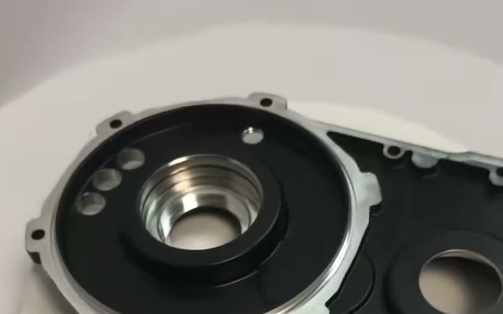
A black-anodized gearbox housing with its bearing bores and sealing face held bare.
What to keep the finish off
On a robot joint or arm, three groups of features usually need to stay free of the anodic film:
- Bearing bores and other toleranced fits. Masked, or machined after anodize where the boundary or final size is critical. On gearbox and motor housings we have masked the H7-class bearing bores through black anodize.
- Threads. Small threads such as M2.5–M4 in thin housings are often masked so the film does not affect fit, torque or thread engagement. Your drawing should say which threads are masked rather than leaving it to judgement.
- Electrical bonding and grounding faces. The anodic film is an electrical insulator, so any face or tapped hole that bonds the housing to the frame, a shield or a ground screw must be bare. See bare-metal contacts on anodized parts.
The alternative to masking is finish-machining after anodize: the part is machined with stock left on the critical features, blasted and anodized all over, then re-fixtured and the bare features milled and tapped. It costs a second setup, but it gives a sharp boundary and a final dimension that does not depend on a mask seal. Masking is generally the economical choice for repeat batches; post-anodize machining is the safer choice where the boundary or the size is critical.
When paint or powder coat is the better answer
Some robots carry an industrial-design colour — a brand yellow, a specific white or grey — defined in a CMF document or by a colour reference. Dyed anodize is not the natural route to that. Colours from paint and powder coat are easier to hold consistent than dyed anodize, organic anodizing dyes can fade with UV exposure, and a painted colour does not shift between 6061 and 7075 the way a dyed film does. Bright dyed colours such as yellow are possible in anodize, but where a defined colour has to be held across many parts, paint or powder coat is usually the better fit. The trade-offs are covered in anodizing vs powder coating, and finish samples are in the finish library.
- Actuator gearbox, stator and motor casings in 6060-T6 and 6061-T6: bead blast and black anodize, with threads masked and bare-metal grounding features finish-milled and tapped after anodize.
- Humanoid hip and torso shells and joint frames quoted in black or natural bead-blast anodize; joint caps in grey-black anodize; joint motor housings and 7075 output shafts in hard anodize.
- Gearbox and motor housings in 6061-T6, black Type II anodize with bearing bores and threads masked, in batches of roughly 65–130.
- Robot-arm parts in 6061 and 7075 painted to the customer's specified colour.
What to put on the drawing
- Finish type, class, colour and thickness, for example "MIL-PRF-8625 Type II Class 2, black, bead blast before anodize".
- Every masked feature, marked on the drawing or coloured in the STEP file.
- Whether bore tolerances apply before or after finishing.
- Which faces are cosmetic, so they are protected in handling and packing.
- A colour reference: an existing part or an approved sample.
We machine robot joints, housings and arm parts from single prototypes to production batches, with no minimum order and quotes within 48 hours. Certification is ISO 9001:2015, IATF 16949:2016 and AS9100D, and an NDA is available on request. See robotics CNC machining, or send your drawings for a quote.
Common questions
Why are robot joints bead-blasted before anodizing?
Blasting gives the aluminium an even matte or satin texture before the anodic film forms, which evens out light machining marks and gives a more uniform appearance across a family of parts. Anodizing then adds a hard, corrosion-resistant oxide layer and, if dyed, the colour.
How much does anodizing change a bearing bore?
Roughly one third of the film grows outward for Type II and about half for Type III. A 3–5 µm Type II coat closes a bore by about 2–3.5 µm on diameter; an 8–25 µm hard coat by about 8–25 µm. Tight bearing fits are normally masked or finish-machined after anodizing.
Can you match the black or colour of our existing parts?
We match to a physical sample or approved first article as closely as we can, but dyed anodize is not a guaranteed exact match: shade varies with alloy, film thickness and dye lot, and 7075 dyes differently from 6061. We confirm the colour on a sample before the batch runs.
Should robot arm covers be anodized or painted?
Anodize suits structural parts that need a hard, thin film and bare conductive areas where masked. Where the industrial design specifies a defined colour to be held across many parts and alloys, paint or powder coat is usually the better fit.
Which features should be masked?
Bearing bores and other toleranced fits, threads where the film would affect fit or torque, and any face or hole that carries an electrical bond or ground, since the anodic film is an electrical insulator. Mark them on the drawing or colour them in the STEP file.