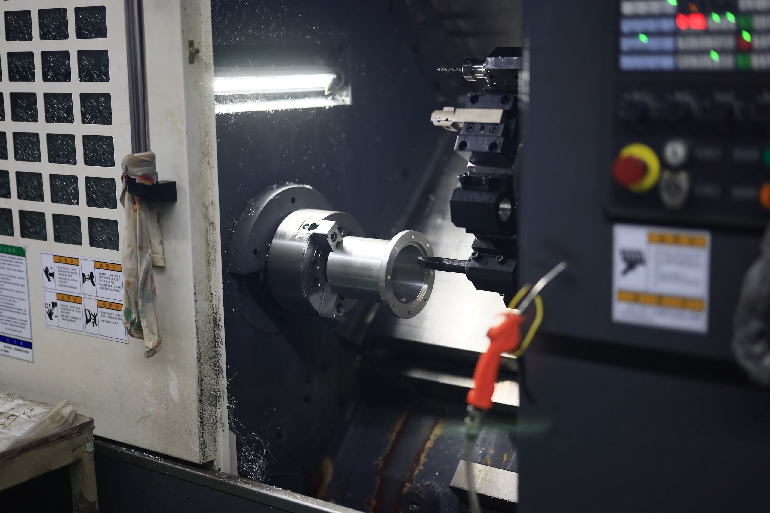
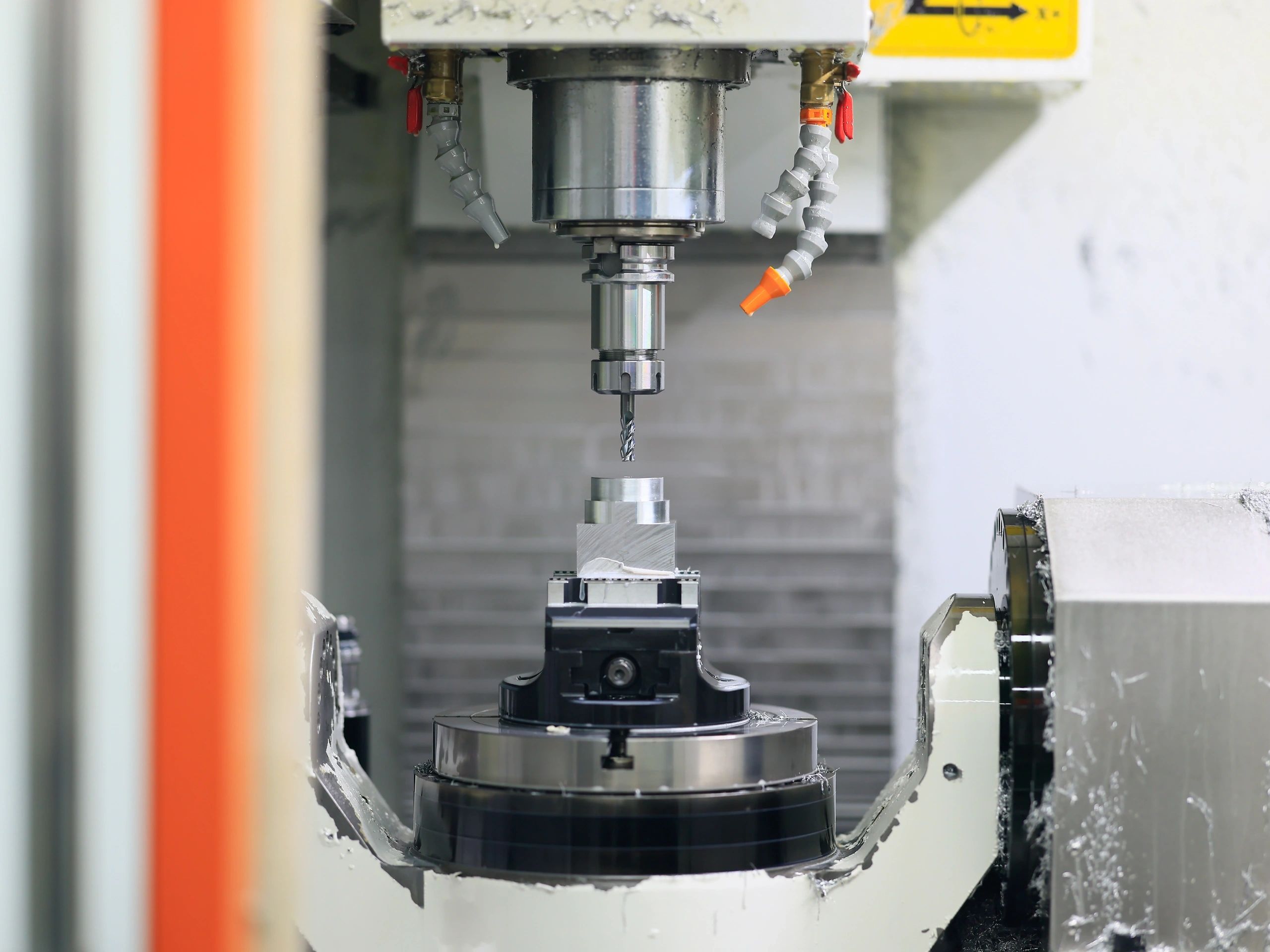
Thin walls are how you take weight out of a part, and weight is range, speed or payload you get back. But a thin wall is also the hardest feature to hold in tolerance: the same thinness that saves weight makes it flex under the cutter and move after it leaves the machine. Here's what's really going on, what we can hold, and how to design a thin-wall part that stays cheap and flat.
Why thin walls are hard: stiffness falls off a cliff
A wall's resistance to bending doesn't drop in proportion to thickness, it drops with the cube of it. Halve a wall from 2 mm to 1 mm and it isn't twice as floppy, it's roughly eight times floppier. So the number that matters usually isn't wall thickness on its own, it's the aspect ratio, the wall's unsupported height divided by its thickness. A short, stout rib is rigid; a tall, thin one is a cantilever waiting to chatter.
Halve a wall's thickness and it isn't twice as floppy, it's about eight times. The unsupported height-to-thickness ratio, not thickness alone, sets the limit.
What's machinable
The limit usually isn't the wall thickness on its own, it's the ratio of wall height to thickness. A short 0.6 mm wall is easy; a tall one of the same thickness flexes away from the tool and chatters. These are the ranges we plan around for aluminium:
| Feature | Comfortable | Feasible (adds cost) |
|---|---|---|
| Wall thickness | ≥ 1.0 mm | down to ~0.5 mm |
| Floor thickness | ≥ 1.0 mm | down to ~0.6 mm |
| Wall height : thickness | ≤ ~10 : 1 | up to ~15–20 : 1 |
The three ways a thin part goes wrong
- Tool-pressure deflection. The cutting force pushes the wall away, so it finishes thicker than programmed, and because the wall is floppiest at the top, often tapered or bell-mouthed. Push harder to correct it and it chatters. You sneak up on a thin wall, you can't bully it to size.
- Released residual stress. Rolled and extruded stock is a balanced tug-of-war of internal stress. Remove material, especially from one side, and the balance breaks: the part bows or twists, sometimes after it comes off the machine, so it measures fine at the spindle and out-of-flat an hour later.
- Thermal growth. Aluminium expands about 23.6 µm per metre per °C. A thin section has little mass to absorb heat, so it grows locally during the cut and shrinks after, enough to walk a tight bore out of tolerance if it's run hot and dry.
Design moves that keep it cheap
- Don't over-thin. A 1 mm wall is routine; 0.5 mm is slow and fragile. Thin only where weight or function truly demands it.
- Add a rib or gusset. A small stiffening rib lets a thin wall stay flat far more cheaply than tightening the tolerance on a bare wall.
- Generous corner radii. Internal radii let us use a larger, stiffer tool that deflects less, faster and more accurate at once.
- Tolerance flatness only where it counts. A tight flatness callout on a thin part means extra passes and stress relief, ask for it on the faces that mate, not the whole part.
- Keep features symmetric. Pockets balanced about the part's centre release stress evenly and bow far less than a deep pocket cut on one side only.
- Pick a stable material. For flatness-critical plates, cast tooling plate (such as MIC6) starts far flatter and stays flatter than standard rolled stock, ask us at DFM.
What we can hold
On a sensibly designed thin-wall part we hold general tolerances to ISO 2768-m and tighten to ±0.005 mm on the features that need it. Flatness and wall thickness on tall, thin sections are the dimensions to discuss up front, those are where the part's own flexibility, not the machine, sets the limit. Tell us which faces and walls are functional and we'll tell you honestly what's holdable and what it costs.
Quick rule
Keep walls at 1 mm and a modest height-to-thickness ratio where you can, add a rib instead of chasing a tighter tolerance, and call out flatness only where it mates. Send the model and we'll flag the thin features and advise at DFM review.