Anodizing creates an electrically insulating aluminium-oxide layer on the surface, so any grounding or bonding area has to be kept uncoated or have the coating removed afterwards. There are two common approaches: mask the area before anodizing, or machine the coating away after it.
Why anodizing interrupts electrical continuity
Anodizing converts the outer skin of the aluminium into aluminium oxide. That layer is what gives the part its corrosion resistance, its hardness and its colour — and it is also a dielectric. A few micrometres of anodic coating can raise contact resistance enough to prevent reliable electrical bonding.
How much this matters depends on the part. For many purely structural components it is irrelevant. For electrically bonded housings, actuator components and shield interfaces it can be critical — an actuator housing bonding the motor casing to chassis ground, a joint housing carrying a shield termination, a stator cover with an M2.5 grounding screw.
On these parts, surface-finish requirements directly affect electrical performance, so the conductive contact areas should be defined before the machining and finishing process is planned.
The dashed line is the as-machined surface. Everything to the left of the divider is coated; everything to the right was masked and therefore did not receive the anodic coating.
Route 1 — mask before anodizing
Masking prevents a selected face, bore or thread from receiving the anodic coating. Common masking methods include plugs, die-cut masking, purpose-made silicone stop-offs, and hand- or robot-applied masking lacquer; the appropriate method depends on geometry and production volume.
- Nothing is disturbed after coating. The masked feature largely retains its pre-anodize machined dimension — no additional setup, no re-fixturing, and no risk of chipping the coating at a cut edge.
- Masking is well suited to production quantities. Once the mask tooling exists, the incremental cost per part is generally low and relatively stable across a production run.
- It protects threads. Coating buildup on the thread flanks can reduce clearance and interfere with assembly; masking is the usual answer, and the face around the hole can be protected in the same operation.
Masking generally produces a less sharply defined coating boundary than machining, because there is always a small transition where the mask sat. The rack that carries the part through the process also leaves a contact point that cannot be coated, so it is worth placing that point on a non-functional face at the drawing stage rather than discovering it at inspection.
Masking is a well-established production process, but its repeatability depends on mask design, application and condition. Over repeated cycles, worn plugs or fixtures can allow small amounts of solution to reach the protected area, leaving coating where the drawing called for bare metal.
This variation is typically detected during inspection rather than controlled by the machining operation itself. Where the exposed-metal boundary or the final dimension is especially critical, post-anodize machining gives tighter control.
Route 2 — finish-machine after anodizing
The alternative is to anodize the whole part and then selectively remove the anodic coating where bare metal is required: a light finish cut on a face, a spotface beneath a screw head, a bore taken to size, or a thread cut after coating.
The advantage is control: the coating is removed by a cutting tool working to a toolpath, so the location and size of the exposed area do not depend on how a mask performed in the process tank.
- The boundary can be controlled more precisely — the bare-metal boundary and area are defined directly by the machining toolpath rather than by how well a mask was applied.
- The final dimension is controlled directly. Where a feature is both a precision fit and a contact area, machining it last removes the coating-thickness allowance from the calculation.
- It requires an additional setup — re-fixturing a finished, coated part with additional handling precautions to avoid damaging the finished surface, plus the risk of chipping the coating at the edge of the cut.
- It intentionally removes local corrosion protection from the machined area. That is the intent, but it should be a deliberate decision rather than a side effect.
Which route for which feature
The question that settles it is what the bare-metal area is for. Many masking requests are driven primarily by dimensional requirements rather than conductivity — a tapped hole whose nut has to run freely, a seal groove, a locating hole. There the concern is that film build-up disturbs a size, and if a small amount of coating reaches the protected area, the result may be a cosmetic defect or a dimensional deviation.
Where the reason is electrical, the consequences of partial anodic coverage are different: coating left on part of a grounding pad raises contact resistance rather than shifting a dimension slightly. Masking is used successfully for electrical contact areas across the industry, so this is a selection question rather than a rule.
In practice we choose between the two on required contact resistance, boundary precision, corrosion protection, production volume and repeatability. Post-anodize machining is most useful where the conductive area or its dimensions must be tightly controlled.
| Feature | Why it stays bare | Usual route |
|---|---|---|
| Tapped hole, nut must run freely | Dimensional — coating buildup on the thread flanks can interfere with assembly | Mask |
| Sealing groove | Dimensional — film changes the section and the seal squeeze | Mask |
| Dowel / locating hole | Dimensional — the finished position and size must remain within tolerance | Mask |
| Bearing bore or other precision fit | Dimensional, but the final tolerance must be controlled | Mask, compensate for coating buildup, or post-machine where the available tolerance is limited |
| Grounding / bonding pad | Functional — it must maintain a low-resistance electrical connection | Masking is often sufficient; post-machine where boundary location or final dimensions require tighter control |
| Grounding-screw boss or thread | Functional — it is part of the grounding path | Mask or post-machine depending on contact-resistance and boundary requirements |
| Shield termination / EMC bond face | Functional — partial anodic coverage can increase contact resistance and reduce bonding reliability | Mask or post-machine depending on contact-resistance and boundary requirements |
Production quantity changes the cost trade-off within the dimensional group: the higher the quantity, the more masking tends to pay. It shifts it less for electrical requirements, where the concern is contact resistance rather than a few micrometres of size.
What drives the cost of post-anodize machining
Machining after anodizing is not priced by how much metal comes off — the actual material removal is usually minimal. The main cost drivers are fixturing, handling and setup: designing or adapting a fixture that holds a finished, coated part without marking it, plus the labour of loading and indicating each piece.
That gives you a design lever worth using before the design is released. Where possible, group post-anodize machined features so they can be completed within the same operation and setup. If every one of them can be reached in a single milling setup, adding another accessible feature — a tapped hole, a second pad, a spotface — may add little incremental machining cost, because it can be completed within the same setup. But if one bare zone is a turned feature and another is a milled feature, the part needs an additional fixture and setup, and the cost increases more noticeably.
On planet carriers and joint housings this is usually easy to arrange, because the conductive faces tend to sit at the same end of the part. Grouping these features during the design stage can reduce later fixturing and setup cost.
What the film does to your dimensions
The coating does not simply sit on top of the part. Part of it builds up outward from the original surface and part of it penetrates into the parent metal, so an external surface grows and a bore diameter decreases. On a diameter the effect applies from both sides.
The split is not the same for both processes. As a nominal rule a Type II sulphuric coating builds up roughly a third of its thickness outward, while a Type III hardcoat is closer to half and half. Actual dimensional change varies with alloy and process conditions, so the figures below are nominal — we confirm the critical fits on your part rather than working from a table.
| Process | Coating thickness | Change per face | Change on a diameter | Microhardness |
|---|---|---|---|---|
| Our usual Type II (cosmetic) | 3–5 µm | ≈ 1–1.7 µm | ≈ 2–3.5 µm | ≈ 300–400 HV |
| Our usual Type III (hardcoat) | 8–25 µm | ≈ 4–12.5 µm | ≈ 8–25 µm | ≈ 400–600 HV |
Anodic coating hardness is measured as microhardness in Vickers (HV), not Rockwell C — the coating is a thin ceramic layer and a macro-indenter is not valid on it.
A worked example. A Ø50 H7 bore has a tolerance band of +0.025 / 0 mm, so the total tolerance band is 25 µm. With a 4 µm Type II coating, the bore diameter decreases by roughly 2.5–3 µm, around an eighth of the band, which can often be accommodated without special compensation, depending on the starting machined size. At a 20 µm Type III coating it closes by roughly 20 µm, a large portion of the available tolerance band, before machining variation is included in the tolerance stack. A bore in that situation is normally masked, machined oversize by a calculated allowance, or finish-machined after coating.
Where the tolerance is measured — one of the most important notes on the drawing
A drawing that specifies Ø50 H7 and hard anodized without stating the sequence can be read two ways, and the two interpretations result in different finished dimensions. Read as pre-coating, we machine to the drawing dimension and the finished bore ends up undersize. Read as post-coating, we machine oversize by a calculated allowance, mask the bore, or machine it after coating.
Practice varies: some drawings dimension the machined substrate and control the coating separately in the finish notes. Where surface treatment can affect a critical tolerance, we confirm whether the requirement applies before or after finishing rather than making an assumption. Stating it on the drawing eliminates this ambiguity.
Calling it out on the drawing
FINISH: BEAD BLAST + BLACK ANODIZE (TYPE II)
TOLERANCES APPLY TO FINISHED PART AFTER SURFACE TREATMENT
EXAMPLE DRAWING-SPECIFIC SYMBOL:
⌵x = NO ANODIZE, BARE METAL — ELECTRICAL CONTACT
· FACE A (GROUND PAD)
· 4× M2.5 AND SURROUNDING FACE
· ⌀50 H7 BORE
A defined symbol with a clear legend is usually easier to interpret than a long general note: it puts the requirement on the face it applies to, and allows the programmer to identify the applicable surfaces directly from the drawing. Say why a zone is bare — "electrical contact" tells the shop it is functional, not cosmetic, and that rack marks, residual coating or other surface defects in that functional area may not be acceptable.
Bare aluminium re-oxidises — design for it
Aluminium forms a native oxide within minutes of being cut. It is only a few nanometres thick, unlike the anodic coating, but it means a bare contact face is never entirely oxide-free.
In practice the joint is designed around it. Adequate fastener preload, serrated washers designed to disrupt the oxide layer, and properly designed bonding interfaces can establish reliable low-resistance contact through it.
What this does mean is that a bare-metal area is not a permanent cosmetic feature. It will dull, and it may corrode over time, particularly in humid or aggressive environments, where the anodic coating would have protected it. Keep bare-metal areas as small as the electrical function allows, and put them where the assembly covers them.
When conductivity is required over a larger area: chemical conversion coating
Where most of the surface has to conduct, masking the majority of the part is not a practical approach. A chemical conversion coating — chem film or chromate conversion coating, specified under MIL-DTL-5541 — forms a very thin conversion layer that provides corrosion protection while maintaining much lower contact resistance than anodizing. Class 3 is intended for applications where low electrical contact resistance is important, such as bonding surfaces and chassis interfaces.
MIL-DTL-5541 Type II covers conversion coatings that contain no hexavalent chromium, and is commonly selected where RoHS compliance is required. Specific regulatory compliance should be confirmed against the chemistry and supplier documentation used for the job.
It is not a substitute for anodizing where hardness, wear resistance or a deep black cosmetic finish are required. It is better suited to applications where the driving requirement is corrosion protection with retained conductivity across a whole surface rather than a localised pad.
Industry reference points for the electrical side: MIL-A-8625 covers anodic coatings and notes that they are insulating; MIL-DTL-5541 Type II Class 3 covers conductive conversion coatings; MIL-STD-464 is where the commonly referenced 2.5 mΩ value comes from, and there it applies to an individual faying-surface connection rather than to a whole installation.
How we hold it
The parts this guide covers — actuator casings, robot joint housings, gearbox covers, planet carriers — often combine a precision bore, a thin wall and a functional bare-metal area on the same component. Where geometry requires it, we use 5-axis machining so key bores and mating faces can be established within the same coordinate system, reducing error introduced by repeated re-fixturing. Post-anodize bare-metal areas are completed in a separate repeatable setup when required.
Critical finished dimensions are verified after surface treatment using the measurement method appropriate to the feature, including CMM inspection where suitable (SEREIN CROMA-776, 700 × 700 × 600 mm, Renishaw PH10T head, in a temperature-controlled room), with a 2.5D optical vision measuring machine available for suitable planar features.
Related reading: Anodize Type II vs Type III for the finish itself, tolerances and ISO 2768 for what to tighten and what to leave general, and the application pages on planet carrier machining and robot actuator housing machining.
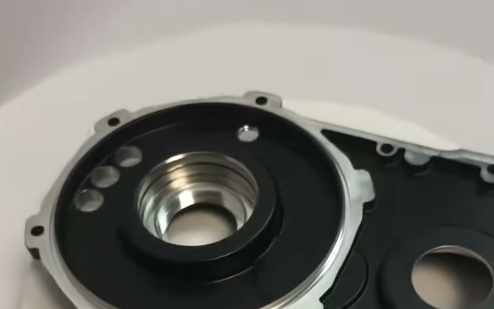
A black-anodized gearbox housing with its bearing bores and sealing face held bare. The bores are fits; the flange face carries the joint.
Common questions
Is anodized aluminium conductive?
No. The film is an aluminium-oxide ceramic and behaves as an insulator. Any surface requiring reliable electrical contact should either remain free of anodic coating — masked before anodizing — or have the coating removed afterwards.
Is it better to mask before anodizing or machine after?
It depends what the bare-metal area is for. Where the reason is dimensional — a tapped hole a nut must run freely in, a seal groove, a locating hole — masking is the usual choice and scales well. Where the reason is electrical, masking is also widely used, but coating left on part of a contact area raises contact resistance, so we weigh required contact resistance, boundary precision, volume and repeatability. Post-anodize machining is most useful where the conductive area or its dimensions must be tightly controlled.
How much does anodizing change a dimension?
Part of the coating builds up outward and part penetrates into the metal, so an external face grows and a bore closes. The split differs by process: nominally about a third outward for Type II and about half for Type III. Across our usual ranges that is roughly 1–1.7 µm per face at 3–5 µm Type II, and roughly 4–12.5 µm per face at 8–25 µm Type III, doubled on a diameter. It varies with alloy and process, so we confirm critical fits per job.
Do tolerances apply before or after surface treatment?
Where surface treatment can affect a critical dimension, we confirm whether the tolerance applies before or after finishing rather than relying on an unstated assumption. It is one of the most consequential ambiguities on a drawing, because it directly affects the machining and finishing route.
Will a bare-metal area stay conductive?
A native oxide a few nanometres thick reforms within minutes. A properly designed clamped joint, serrated washer or bonding interface can establish reliable metal-to-metal contact through it, which is why grounding joints are designed around clamped contact rather than a permanently pristine surface.
Can you keep a threaded hole bare while anodizing the rest?
Yes — threaded holes and the face around them are routinely held bare through bead blast and anodize by masking. That is one finish with a protected zone, which is a different proposition from putting two different coatings on two zones of the same part.