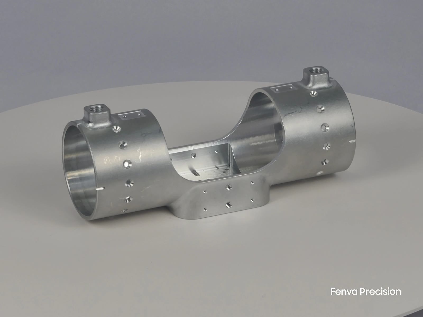
The machining challenge in a robot joint or actuator housing is not usually one individual feature. It is maintaining the relationship between several precision features on a thin-walled structure designed to minimise mass.
Coaxial bearing bores, a flat output flange, a thin structural wall and a bare-metal contact area all have to be controlled on the same component. This guide covers how each is held, and why they are best machined in one setup.
Coaxial bores drive gear alignment
The housing maintains alignment of the gearset along a common axis. Whether the drive is a planetary stack, a strain-wave unit with a circular spline, or a cycloidal design, the bearing seats at each end of the housing define where that axis actually sits. If they disagree, the gears run misaligned regardless of the accuracy of the gears themselves.
Bearing and spline seats in this class of part are commonly specified at H7, and H6 where the design is tight on runout. For example, depending on the applicable ISO size range, a 70 mm bore gives a band of roughly 30 µm at H7 and 19 µm at H6.
The size band is usually the more straightforward requirement. The harder one is coaxiality between the bores — a relationship rather than a dimension, which measuring each bore individually will not confirm.
Thin walls, and why they move
Robotics housings are weight-driven, so wall thickness is reduced as far as the structure allows — low single millimetres is common. The cutter is rarely the limit. Distortion is.
- Clamping force elastically deforms a thin wall. A wall held round in the fixture can relax into an oval when released, after the bore was machined round.
- Cutting force deflects the workpiece. The tool pushes the wall away and it recovers behind the cut, leaving a bore that measures differently along its length.
- Residual stress redistributes as material is removed. Taking most of a billet away lets the remaining material move, which is why a part can be in tolerance at the machine and out of it the next morning.
The solution is a controlled process rather than heavier cutting or clamping: rough with material left on, allow the part to stabilise between operations, then take light finishing passes with fixturing that supports the wall rather than squeezing it. It is slower than cutting the part in one pass, and it is the difference between a housing that measures correctly once and one that measures correctly every time. The general treatment is in thin-wall aluminium machining.
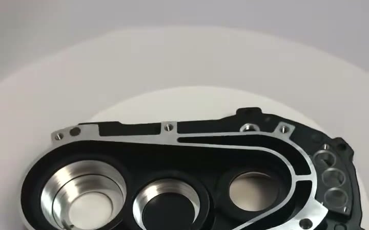
A housing half with its bearing bores and sealing rib held bare through the anodize. The bores are fits; the rib is a joint face.
The output flange has to be flat
The face where the housing meets the output stage — or the next link in the arm — carries the joint. If it is not flat, bolting it up pulls the housing out of shape and pushes the bores it was supposed to protect out of alignment. Worse, the distortion concentrates stress at whichever bolt closes last, which is a fatigue problem rather than an assembly problem.
This is why a flange face on this class of part usually carries two separate controls rather than a generic surface note: a flatness requirement on the face itself, and an orientation requirement — typically perpendicularity — to the bearing-bore datum axis. Flatness is a form control and takes no datum; the relationship to the axis has to be called out separately.
It is also why the face and the bores are best cut in the same setup. Machined separately, their relationship carries the additional re-fixturing error between the two setups.
The post-anodize fit problem
Many aluminium actuator housings are anodized — for wear resistance, for corrosion protection, or to achieve a required cosmetic finish such as black anodizing. That has a direct dimensional consequence for the bores: part of the coating builds up outward from the bore surface, nominally about a third of its thickness for Type II and about half for Type III, so a toleranced bore closes.
Across our usual ranges, a 3–5 µm Type II coating reduces a bore diameter by roughly 2–3.5 µm, which an H7 band usually absorbs. An 8–25 µm Type III hardcoat reduces it by roughly 8–25 µm, which on a 50 mm H7 bore can take up much of the band before any machining variation is counted. Such a bore is normally masked, machined oversize by a calculated allowance, or finish-machined after coating — a decision best taken at quotation rather than at inspection.
Worth knowing when you choose: a production mask is a fixture applied by hand, and its repeatability depends on mask design, application and condition. Over repeated cycles a worn seal can allow solution to reach the protected area. Where the exposed area or the final dimension is especially critical, post-anodize machining gives tighter control.
The same page covers the other half of the problem: keeping bonding and grounding faces conductive. See bare-metal contacts on anodized parts.
Bare zones, bonding and EMC
Because an actuator housing encloses the motor, encoder and drive electronics, the housing often forms part of the system's EMC and grounding strategy. Shield terminations, chassis bonds and grounding screws all require a metallic path, and the anodic coating that protects the housing will interrupt that path unless specific faces are kept uncoated or machined afterwards.
Practically, that means the housing drawing should identify: the ground pad and what it bonds to, any threaded hole taking a grounding screw, and whether the bare-metal area is functional (where rack marks, residual coating or other surface defects may not be acceptable) or merely cosmetic. Bonding requirements in this space are often written against MIL-STD-464, where the frequently quoted 2.5 milliohm figure applies to an individual faying-surface connection rather than to a whole installation — worth knowing when a drawing note quotes it without context.
Machining the set, not just the part
An actuator is rarely a single part. A build typically includes a casing, a gearbox cover, a stator cover, an electronics cover, an output shaft, one or two planet carriers, an input shaft and a rotor support — parts that have to fit each other, not only satisfy their own drawings individually.
Machining them as a matched set and inspecting them together catches interface problems that per-part inspection can pass over: a bore and a shaft each in tolerance but at opposite ends of their bands, or a cover flange that is flat but not parallel to its mating face. For prototype builds, successful assembly often depends on controlling these interfaces as a system rather than evaluating each component in isolation.
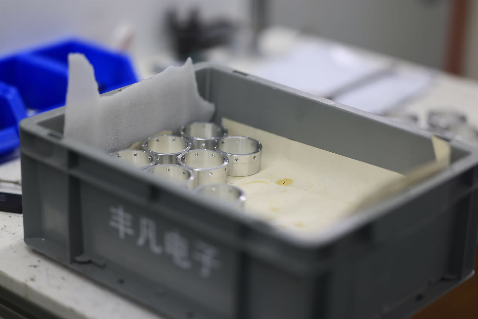
Turned housing sleeves in production. Prototype and production run on the same floor, so the process that proves out on the first pieces is the process that scales.
How we hold it
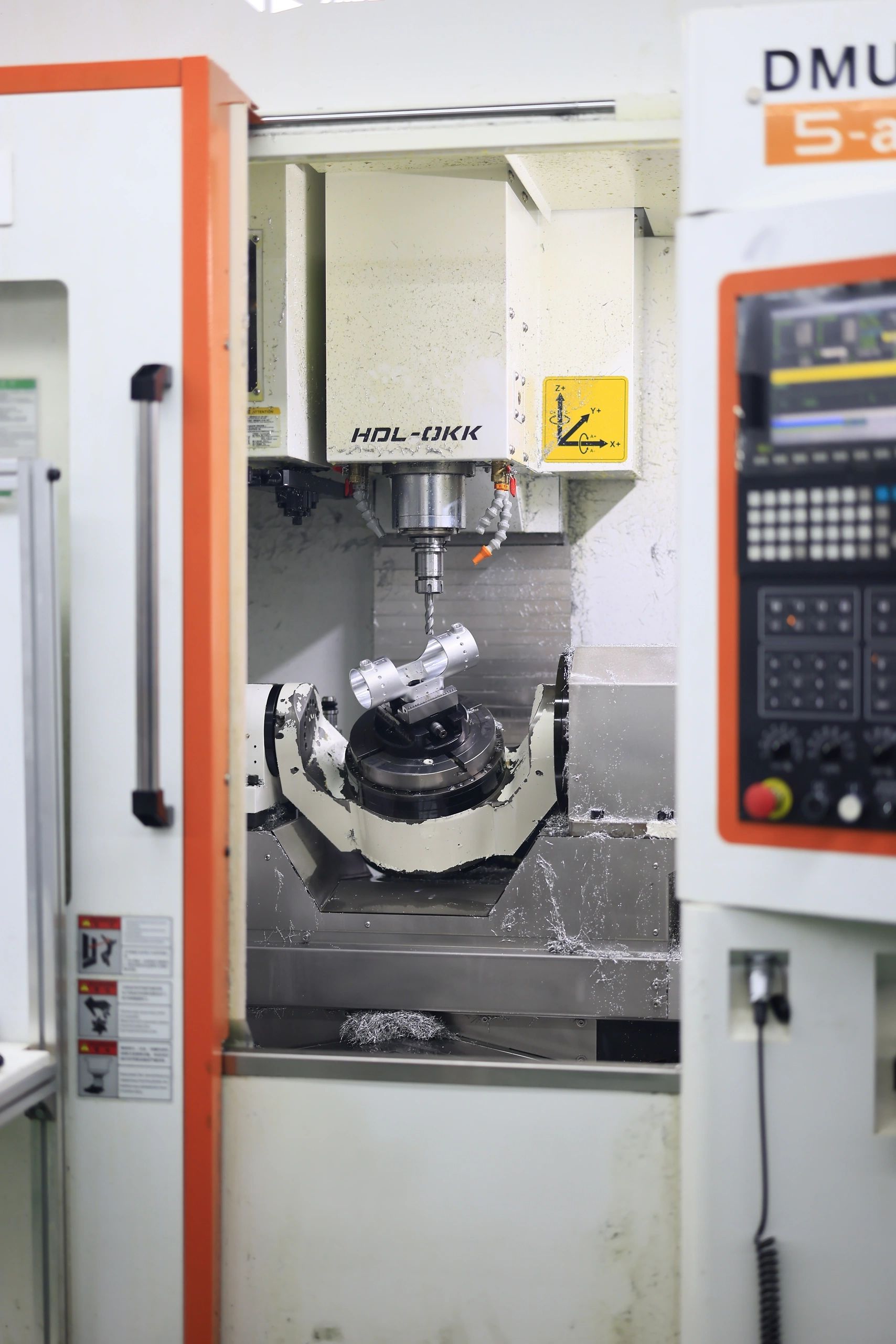
Housings run on simultaneous 5-axis so the bores, the flange face and the bare-metal areas share a single setup and their mutual position depends on the machine rather than on re-fixturing. Milling envelope is 2000 × 1200 × 800 mm on 5-axis and 2500 × 1200 × 800 mm on 3-axis, with a minimum feature size of Ø0.50 mm; turning goes to Ø500 × 580 mm, with Swiss work on bar from Ø32–42 mm for the shafts.
Inspection is on a temperature-controlled CMM (SEREIN CROMA-776, 700 × 700 × 600 mm, Renishaw PH10T) with a 2.5D optical VMM alongside, reporting coaxiality, flatness and the post-treatment fits as related features. Certification is ISO 9001:2015, IATF 16949:2016 and AS9100D / EN 9100:2018, with batch-level material traceability. Quotes in 48 hours, no minimum order.
Related reading: planet carrier machining, 6061 vs 7075, and the industry page for robotics CNC machining.
Common questions
What tolerance do actuator housing bores need?
Bearing and circular-spline seats are commonly specified at H7, and H6 where the design is tight on runout. What usually matters more than the size band is coaxiality between the bores at each end of the housing, because that is what keeps the gearset aligned along its axis.
Why machine a housing in one setup?
Coaxiality, flange perpendicularity and the bare contact zone are relationships between features, not properties of any one feature. In one simultaneous 5-axis setup those relationships depend on the machine's accuracy; split across setups they depend on how well the fixtures agreed, which is a larger and less predictable error.
How thin can a housing wall be?
Weight-driven robotics housings often run walls in the low single millimetres. The limit is rarely the cutter — it is distortion, because a thin wall moves under clamping load and springs back under cutting force. The answer is staged machining with roughing, a settling pause and light finishing passes, plus fixturing that supports rather than squeezes.
Do you machine the whole actuator set or single parts?
Either. Housings, covers, output shafts, planet carriers and bearing flanges can be machined as a matched family and inspected together — usually what a prototype build actually needs, because the parts have to fit each other rather than just fit their own drawings.
Can grounding zones be kept bare through anodizing?
Yes. Faces and threaded holes carrying an electrical connection are held bare through bead blast and anodize by masking, or the film is machined away afterwards where the boundary has to be exact or the feature is also a toleranced fit.