A handful of design choices decide whether a part is fast and economical to machine or slow and risky to make. Below are the ones that matter most, with simple rules of thumb that keep a design easy to manufacture.
The rules of thumb
| Feature | Rule of thumb | Why it matters |
|---|---|---|
| Wall thickness | ≥ ~0.5 mm (metal), ~1.0 mm (plastic) | Thin walls vibrate and warp under the cutter |
| Internal radius | ≥ the tool radius (or add a corner relief) | A round cutter can't carve a perfectly sharp inside corner |
| Hole / pocket depth | ≤ ~4–6× the tool diameter | Go deeper and the tool flexes, so it needs special tooling |
| Threads | Standard size + class; avoid bottoming | Keeps tooling simple and cost down |
| Chamfers | A chamfer running into a wall stops short of the edge | The cutter needs room to pull away |
| Text / logos | Engrave (recessed), ≥ ~0.25 mm stroke | Raised text means cutting away the whole surface around it |
| Tolerances | General tolerance + flagged critical dims | Tight callouts multiply both machining and inspection cost |
Wall thickness
Below about 0.5 mm in metal, a wall is too thin to resist the cutting force: it vibrates (machinists call this "chatter") and warps, leaving a rough surface and dimensions that fall out of tolerance. The remedy is straightforward — thicken the wall, or reinforce it with ribs.
Internal radii
Milling cutters are round, so a milled inside corner always carries the radius of the tool — it can never be perfectly sharp. Give each inside corner a radius at least as large as the tool, or add a corner relief (a small undercut tucked into the corner). A dead-sharp internal corner can't be milled at all; it forces slow, costly EDM (electrical discharge machining, which erodes the metal with electric sparks instead of a cutter). When in doubt, an R1 or R2 internal radius is a safe default for general parts.
Hole & pocket depth
A cutting tool can only reach so far before its performance degrades. Past roughly 4–6 times its own diameter, it deflects off course and struggles to clear chips from the bottom of the cut. Deep holes and pockets remain feasible — please flag them early so we can plan the right tooling.
Threads
Use standard thread sizes and fit classes so we can run off-the-shelf taps. Where possible, avoid bottoming threads — threads cut all the way to the floor of a blind hole — because the last turn or two is difficult to form cleanly and slows production.
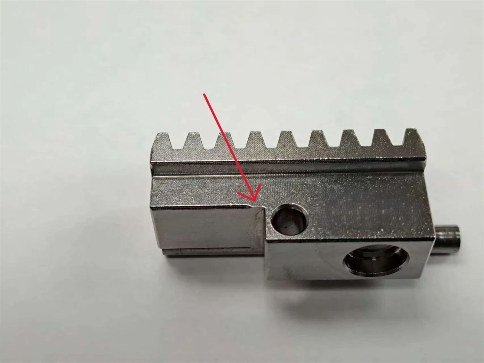
Chamfers
A chamfer — the angled bevel that softens a sharp edge — usually can't reach all the way into a corner where it meets a wall or shoulder. The cutter needs room to pull away from the wall, so it stops a little short and leaves a small un-chamfered stub right at the corner (the photo above shows exactly this). That's a normal consequence of how the tool moves, not a defect. If a chamfer truly must run fully into a corner, flag it at the drawing stage so we can plan tool access or relieve the adjacent face.
Tolerances
A tolerance is how much a dimension is allowed to drift from the number on the drawing. Hold every dimension to a tight tolerance and the same part can cost up to ten times what it would at a general tolerance (ISO 2768-m, a common default). So tighten only the dimensions the part's function actually depends on, and leave the rest at general tolerance. For the full picture, see how ISO 2768 general tolerances work.
Three quick mistakes
- Sharp internal corners — add a radius or corner relief so the part can be milled instead of EDM'd.
- Deep, narrow pockets — the tool flexes and chips can't clear from the bottom.
- Tall, thin walls with no ribs — they vibrate and warp under the cutter.
The payoff
We review every drawing and flag these issues before machining begins — but addressing them in the design from the start saves an entire revision cycle.